 How different antennas can battle external noise.
 Why I should use a loop antenna.
 Buried antennas for areas with restrictions.
 How long a Beverage antenna should be.
 Active antenna can overcome local interference.
 Outdoor antennas forbidden? Go for the Snake.
 Find the optimum antenna height for a dipole.
Down To Earth
Antennas
By Joseph
Buch
NASWA Journal, December 1992, and
January 1993
Most antenna handbooks optimize antenna design for maximum effectiveness
for transmitting applications. Design engineers go to great lengths
to maximize efficiency, minimize mismatch to the feedline, and
maximize radiation in the direction of the horizon with as little
upward radiation as possible for maximum distance per hop.
We will look at the applicability of these concepts for
the SWL and explore why you may want to adopt totally different
approaches for your DX receiving antenna.
We will show why antennas close to the ground work well
for receiving.
We will show why small, active antennas can actually outperform
full size dipoles and random wires.
And we will examine a new adaptation of the wave antenna
which was successfully used in the sands of Iraq.
 Antennas
that couple maximum energy out of a transmitter will also
couple maximum energy into a receiver. The sensitivity of modern
receivers is so good, however, that the ability to hear a weak
station is determined more by the atmospheric noise and interference
on the listening frequency than by the signal level delivered
to the receiver. This noise is especially limiting on the tropical
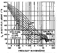
band frequencies below 5.9 MHz. To test your receiver, disable
the receiver AGC, remove your antenna from the input and substitute
a 50 ohm resistor. If the speaker noise is less on the resistor,
your receiving sensitivity is limited by outside noise. Try this
on several frequencies. Your results should look something like
the curves of Figure 1. Thus, the performance of a receiving antenna
depends upon its ability to discriminate between the desired signal
and the external noise environment, not the efficiency of the
antenna. Antennas
that couple maximum energy out of a transmitter will also
couple maximum energy into a receiver. The sensitivity of modern
receivers is so good, however, that the ability to hear a weak
station is determined more by the atmospheric noise and interference
on the listening frequency than by the signal level delivered
to the receiver. This noise is especially limiting on the tropical
band frequencies below 5.9 MHz. To test your receiver, disable
the receiver AGC, remove your antenna from the input and substitute
a 50 ohm resistor. If the speaker noise is less on the resistor,
your receiving sensitivity is limited by outside noise. Try this
on several frequencies. Your results should look something like
the curves of Figure 1. Thus, the performance of a receiving antenna
depends upon its ability to discriminate between the desired signal
and the external noise environment, not the efficiency of the
antenna.
|
What
kinds of antennas can discriminate against external noise?
|
There
are several designs which have proven useful. There are three
general classes of receiving antenna which can improve the signal
to noise ratio of signals compared to a high, horizontal half-wave
dipole. The first type is the loop. It offers the advantages of
small physical size, portability, and the ability to be rotated
to null out interfering signals The next class of antennas is the
long wire mounted close to or on the ground. Such antennas can exhibit
good directional characteristics but their large physical size prohibits
rotation. Finally, active antennas have proven to be useful. Active
antennas combine a short, inefficient antenna with a low noise amplifier
to make up the signal loss resulting from the short antenna. Active
antennas can often be located in places away from locally generated
interference. The better ones provide good overload characteristics.
The major disadvantages are that most active antennas are expensive
and non-directional.
|
Why
might I choose to use a loop antenna?
|
Loop antennas can be easily constructed by the SWL or purchased
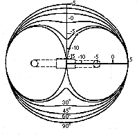
ready to go. The loop antenna pattern has deep nulls at 90 degrees
to the plane of the loop. The pattern of a balanced loop antenna
is shown in Figure 2.
Figure
2.
Loop antenna pattern shows omnidirectional response to high
elevation angle waves.
|
These nulls
are most pronounced on signals arriving at vertical angles near
the horizon when the plane of the loop is vertical. The nulls are
sharp and deep but the maxima are broad allowing the nulls to be
oriented in the direction of the noise without sacrificing much
of the desired signal. The loop won't help much if the interfering
signal is arriving from a high angle or from the general direction
of {or 180 degrees from) the desired signal.
Most of the ham radio antenna manuals mention loops only in passing.
A good design appeared in the 1989 edition of Proceedings. Written
by Joe Farley, the article provides clear plans for the construction
of a remotely-tuned, active loop. Proceedings is published by Fine
Tuning. For those who do not care to roll their own, there are also
several brands of amplified loops available from the usual distributors
that advertise in the commercial SWL magazines. Commercial models
are available in the $100 to $200 range The commercial loops come
with active amplifiers to compensate for the loss of signal resulting
from small physical size. Being inherently frugal (real cheap),
I would prefer to roll my own loop taking advantage of the fact
that the night-time atmospheric noise will usually allow a 30 db
loss in efficiency before the signal to noise ratio is degraded.
|
I
live in an area with outside antenna restrictions. What
about buried or on-the-ground antennas?
|
Another class of antenna uses wires on, near or slightly
below ground level. These antennas are called "wave" antennas because
they extract energy from the wave as it travels down the length
of the wire. The wave antenna achieves improved signal to noise
because it is directional and because its low height minimizes static
induced by charged particles blowing in the air Anyone who has tried
to listen to a normal dipole antenna during a dry desert windstorm
will appreciate this characteristic.
Figure
3.
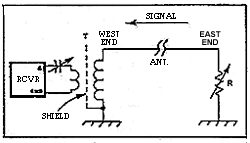
A simple Beverage antenna responds best to signals arriving
from the East if the restistance is adjusted properly.
|
One of the
earliest designs of this type is the "Beverage" antenna. No
it is not a bunch of beer cans soldered end to end. The Beverage
antenna was invented by a team led by Harold H. Beverage and first
described in 1922. The historic article was re-published in the
January 1982 issue of QST magazine and is recommended reading. The
Beverage antenna, shown schematically in Figure 3, is simply a wire
near the ground running in the direction of the desired station
and terminated at the far end in a resistance to ground equal to
the characteristic impedance of the line. This resistance is about
500 ohms and can be made variable for exact adjustment to minimize
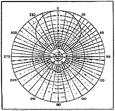
response off the back. A typical Beverage pattern is shown in Figure
4.
|
How
long should a Beverage antenna be?
|
The length of a Beverage antenna can range up to thousands
of feet for long wave reception. Mr. Beverage stated in a letter
publish in QST in December 1981 that Beverage antennas should not
be longer than one wavelength at the frequency of interest. A wavelength
at 3 MHz is 100 meters and scales inversely with frequency. So one
wavelength at 6 MHz is 54 meters and at 1.5 MHz is 200 meters.
Figure
4.
Beverage antenna directional pattern after optimizing the
terminating restistance.
|
Because the
wave in free space travels faster than in the antenna, the longer
the antenna, the greater the phase difference between the current
in the antenna wire and the approaching wavefront. Once this difference
becomes greater than 90 degrees, the wave actually starts to oppose
the current in the wire.
Because SWLs rarely read QST, they have been merrily using much
longer Beverage antennas for decades with considerable success.
John Bryant concluded in an article in the 1989 Proceedings that
the optimum length is about 5 wavelengths. Victor Misek says in
his Beverage Antenna Handbook that the optimum length is about two
wavelengths. In the mid 1970s the Canadian Communications Research
Centre in Ottawa sponsored an exclusive study of the use of Beverage
antennas for HF reception That work was briefly described by Belrose
in QST for September 1981. Their work concludes that the longer
the wire, the stronger the signal.
Thus, the experts cannot agree on what length is best which proves
the best length is not terribly critical and probably depends on
local ground conditions. The bottom line is that one or two wavelengths
is probably sufficient for good results.
|
I
live in an apartment. Can an active antenna help overcome
locally generated interference?
|
Yes, active antennas can be used successfully. The balanced
design of this particular antenna is claimed to cancel man-made
noise. Because of their small physical size, these antennas can
often be located in spots chosen to minimize pick up of locally
generated noise. Such interference is often radiated directly from
the source and indirectly by power lines, cable TV shields, telephone
lines, wire reinforcement in stucco walls, metal structure in apartment
buildings, TV antenna lead ins, etc. Every conductor is a potential
re radiator of interference.
The direct signal can add in phase with the indirect signal or the
two can add out of phase resulting in cancellation of the interference.
If you explore your receiving location with a portable SW radio,
you will find places where the cancellation effect can the noise
to diminish or disappear. The null spots are usually quite small
physically. The null locations will tend to change with frequency
because the signals which are canceling each other travel different
distances. As the frequency (and consequently the wavelength) of
the signal changes, the relative phase of the direct and indirect
signals will change. The physical place where they cancel will,
therefore, move. An antenna which takes advantage of this effect
must be physically small enough to stay within the null spot. Full
size antennas occupy a lot of area making it difficult to keep them
within a null region.
Recently, I was plagued by a touch control lamp in my neighbor's
house which radiated strong, wideband buzzing harmonics across the
HF bands. Not knowing immediately what was causing the problem,
I explored my house with a portable SW radio in search of the offending
signal. 1 discovered a location in the attic above my garage where
the interference could not be heard. The direct signal from the
lamp and the signal radiated from the power wiring combined at this
one spot and canceled each other out An active antenna at this spot
would be immune to the interference.
|
Do
active antennas have a downside?
|
Active antennas
have at least two problems. One is susceptibility to overload
and inrermodulalion. The World Radio and TV Handbook did a review
of active antennas a couple of years ago where they evaluated the
various brands for overload performance. I no longer have the book
but remember that the more expensive units gave the best performance
(surprise!). Alan Johnson reviewed a representative unit in the
December 92 NASWA Journal. The other disadvantage, which is common
to all physically small antennas, is that small antennas are more
susceptible to fading than large antennas. HF waves propagated via
the ionosphere can simultaneously arrive at the receiving antenna
after having traveled different distances. When this happens, the
waves can add to improve reception if the waves are in phase. Conversely,
if the waves are out of phase, deep fades of 20 dB or more can result.
Long wire antennas do not experience this effect to the same degree,
because their greater physical size means that somewhere on the
wire, as any instant, the waves do not cancel.
The small antenna can thus experience a momentary gain of 6 dB as
the waves coherently add in phase and momentary fades in excess
of 20 dB when they cancel. The DXer who is patient can wait for
the peaks to occur at the time the ID is given. Murphy's law, however,
dictates that IDs will always occur coincident with fades.
Some engineers combine the active antenna amplifier with the loop
and active vertical whip to provide a compact, efficient, directional
antenna. Techniques also exist to phase active antenna to achieve
multiple simultaneous beams and to generate multiple nulls On interfering
signals. These techniques usually require many antenna elements,
computer controlled phase shifters and specially designed software.
Such antennas have folded application in military and intelligence
circles but the complexity is beyond the capability of SWLs without
PhDs in electrical engineering to implement.
|
I
have a large yard but outside antennas are forbidden. The
copper police keep demanding that t take my antennas down.
What can I do?
|
We have discussed the Beverage antenna which can be mounted
close to the ground. Another design that has gained some popularity
is called the "snake". The snake has been around for about 15
years but knowledge about it has been confined to the radio underground
(pun intended). The snake is shown schematically in Figure 5.

The coax
cable center conductor is connected to the receiver antenna terminal.
The shield is left floating at the receiver. The shield and center
conductor are shorted together at the far end. Aficionados of
this antenna say it has very low noise and is broadbanded. Personally,
I find little theoretical reason to believe this antenna would
be any better than an equivalent length of insulated wire laid
on the ground. With cheap coax selling for $.20 to $.50 per foot'
to extra expense of using coax seems unwarranted.
I have used a 100 foot wire buried a few inches below ground level
for about a year now. The gain is down about 30 dB referenced
to a half wave dipole on most signals around 6 MHz. When conditions
are good the signal to noise at this frequency approximates the
dipole. When signals are disturbed by ionosphere absorption effects,
the additional loss of the buried antenna reduces the already
weakened signals so the dipole has a signal to noise advantage.
In the medium wave spectrum the buried wire outperforms the dipole.
I use this antenna to listen to New York City broadcast stations
during the day from any location some 290 miles to the south.
The buried wire is susceptible to noise pickup where the wire
enters the house. I can hear any computer monitor and printer
doing their things on this antenna but not on the dipole.

One solution
to the local noise problem is to combine the single buried wire
with a coax feedline to shield the line from noise pickup in the
radio room. A design which I intend to try is shown in Figure
6.
The coax cable should only be long enough to keep the wire away
from the noise source. The ohm resistor serves as a load for the
coax cable An improperly matched cable could cause the antenna
to appear to be a near short circuit across the receiver antenna
terminals at frequencies where the coax length is an electrical
quarter wavelength. The 50 ohm resistor provides a reasonable
impedance match which avoids such resonance effects.
|
Is
there an optimum antenna height above ground for a horizontal
dipole?
|
The answer depends on what you want to do. SW broadcasters
targeting international audiences aim for the lowest possible
radiation angle to minimize the number of hops the signal takes
bouncing between the ionosphere and earth. Each bounce increases
the loss. The objective is to provide consistently strong signals
on the target area every day. The SW DXer on the other hand often
waits months for the unusual propagation condition that brings
in that weak Bolivian or Indonesian station.
These anomalous propagation modes are often associated with ionosphere
ducting, grayline, or "whispering gallery" effects with high arrival
angles.
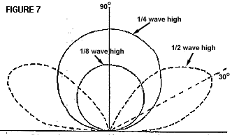
Figure 7
shoves the elevation angle response of a horizontal dipole over
perfectly conducting ground.
Over normal dirt the pattern has the same shape except that the
nulls are less deep and the peaks are not as strong. As the antenna
height is reduced to a quarter wavelength, the pattern shifts
to direct the peak response straight up. At lower heights, the
pattern shape remains nearly constant, only the efficiency decreases.
Antennas which are less than 40 feet high and operating at 6 MHz
and below will have this kind of vertical response pattern.
A high antenna which concentrates reception at low angles will
be the best day to day performer. A low antenna which maximizes
reception from high angles takes best advantage of the unusual
conditions that result in the really rare DX catches. Unusual
propagation is most frequently observed on the tropical bands
because the transmitting stations usually use law dipoles to ensure
good signals at ranges of a few hundred miles. When conditions
are right, the high angle radiation is propagated to the other
side of the world instead of being reflected to the target areas.
The signals arriving from high angles are most efficiently captured
by receiving antennas with high angle patterns.
Murphy must have been asleep when the laws of physics were drafted
because he allowed the easiest antenna to erect to also be the
best for DXing under anomalous propagation conditions.
|


