|
Tuned active antenna
for 5 to 22 MHz
By Adrian Knott, United
Kingdom
During the past few years I have tried Frame Aerials, Ferrite
rod aerials, I even tried the lightning arrestor at one point
(not bad but difficult to resonate and a bit lethal in a thunderstorm)
and active whip aerials.
A one metre whip in free space will develop a fair signal voltage
on HF but there is next to no current ie the impedance is high.
A means of matching to 50 ohms is required. This can be accomplished
by transformer matching but results will not be as good as amplifying
the signal at source. Tuning the whip to resonance is also desirable
since any non linearities in the amplifier stage will tend to
cause cross modulation. If the whip is resonant then it will respond
best to the wanted (and often weak) amateur station and tend to
reject the more powerful commercial traffic on adjacent frequencies.
If the system is tuned then indifferent receivers with a poor
image response will show remarkable improvement.
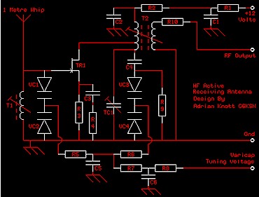
Circuit Description. The whip which is 1 Metre in length
is connected to the hot end of a tuned circuit formed by L1 and
VC1, VC2 (2 back to back varicap diodes). These are biased by
a variable voltage (1 to 9 volts) fed remotely to the unit via
R5, R7, R8 and C5, C6. This network maintains the Q of the tuned
circuit and also filters out any hum and noise picked up en route.
The tuned circuit feeds the gate of TR1, a Field effect transistor
in common source mode which has a very high input impedance and
a moderately low output impedance. The amplified RF is fed to
the primary tap on T2, which along with VC3, VC4 and TC1 from
a second tuned circuit. TC1 compensates for the input capacitance
of the FET and also the self capacitance of the whip
antenna. RF output is available from the secondary of T2. Bias
for TR1 is achieved by virtue of R3. C3 and R4 partially bypass
R3 at HF and the value of R3 may be increased if the unit has
a tendancy to self oscillate.12 Volts is fed to the amplifier
via R1, R2, C1 and C2, another line noise filter. And that's it.
Obviously it needs a remote 12 volt PSU. Something along the lines
of a 3 VA transformer and a 78L12 should be more than adequate
as the unit only draws a few milliamps. The Varicap tuning voltage
can also be derived from a potentiometer across the 12 Volt regulated
line.
Alignment. Set TC1 to it's mid point. Set the varicap tuning
voltage to 1.0 Volts and Adjust T1 and T2 for maximum received
noise at 5.0 MHz. Reset the receiver to 12 MHz and adjust the
varicap tuning voltage to give maximum noise (about 9 volts. Now
trim TC1 for maximum noise. Reset to 5.0 MHz and 1.0 Volts, adjust
T2 for maximum noise. Reset to 12 MHz and readjust Varicap voltage
and TC1 for best signal. Repeat procedure until no further improvement
can be achieved.
For the 12/22 MHz version replace 5/12 MHz with 12/22 MHz.
Components.
R1.....100 Ohm. C1.....22nF.
R2.....1K. C2.....22nF.
R3.....330 Ohm. C3.....22nF.
R4.....100 Ohm. C4.....22nF.
R5.....1M. C5.....22nF.
R6.....1M. C6.....22nF.
R7.....100K. VC1....1/3 KV1236.
R8.....100K. VC2....1/3 KV1236.
R9.....47K. VC3....1/3 KV1236.
R10....47 Ohm. VC4....1/3 KV1236.
TR1....2N3819. Whip...Telescopic 1.0 metre.
T1.....KANK3334. TC1....22pF Trimmer.
T2.....KANK3334.
Notes.
(1) The KV1236 is a triple varicap diode. It is necessary
to literally 'saw' the device into three (be careful) a couple
of strokes with a junior hacksaw in the two notches should be
sufficient. The device will then snap into three. The coil and
the varicaps are available from Cirkit Distribution Ltd in Broxbourne
(I have no connection with the aforementioned company).
(2) For 12/22 MHz operation replace T1/T2 with KANK3335.

Schematic diagram (click for larger picture)

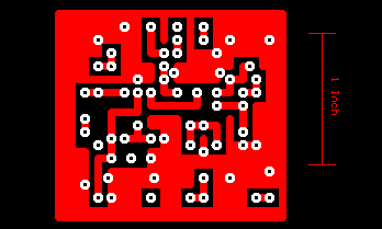
PCB foil (click for larger picture)

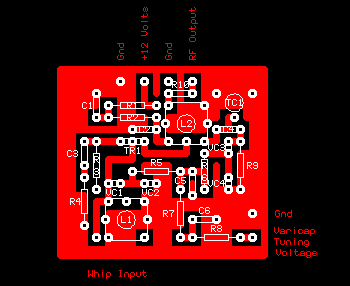
Component layout (click for larger picture)
This
document and the accompanying files are the original work of the
author, Adrian
Knott G6KSN. Please feel free to distribute these files.
|


