|
Construction
project
High-pass
filter
Enjoying Radio, November 1985
(edited by David Newkirk)
A "high-pass"
filter is one designed to pass all signals above a certain
frequency -- the cutoff frequency.
The purpose of this is clear: if you want to receive everything
above, say, 2 MHz, and you're troubled by severe overloading because
of MW broadcast signals (0.535 1.605 MHz), a highpass filter with
the right cutoff frequency will pass the 2-MHz-and-higher frequencies
and leave the lower on" "in the mud."
There
are many, many kinds of filters; there are also low-pass filters,
for instance, that pass all frequencies below the cutoff frequency.
Note that the action about the cutoff frequency is not "as sharp
as a knife"; a high-pass filter with a 2-MHz cutoff frequency
doesn't pass 2001 kHz signals beautifully and chop off 1996 kHz
signals to the point where they're not there. Such filters can
be rated by how many decibels of rolloff (plunge in signal level)
they afford per octave (per halving [for high-pass filters]
or per doubling [for lowpass filters] of frequency. A
6dB-per-octave rolloff would be like reducing signal power to
1/4 its reference value every time frequency was halved or doubled.
Much more
on filters in many electronics/radio texts; a good one that should
be available many places is the 1985 Handbook for the Radio Amateur,
published by A ML, pp. 11-7 to 11-9. Filter are easy to build
and can solve one problems almost magically when properly applied.
Here's Chuck Bolland with the filter he built to chop MW interference
to his SW efforts:
Anyone
having trouble with nearby nediumwave stations swamping his
or her shortwave receiver?
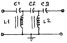
Here is the description of a high pass filter that will help overcome
that problem.
This filter will attenuate all signals below 1700 kHz by at least
20dB. This could be done with an antenna tuner, too, but, unlike
an antenna tuner, this filter does not affect the shortwave spectrum.
In fact, it improves that portion of the spectral by eliminating
the mediumwave noise. This circuit can be found in the book
Ferromagnetic Core Design and Application by Doug DeMaw.
|

L1 and L2:
13 turns #20 insulated wire on T106-Z core from Aside Associates
C1 and C3: 1800 pF
C2: 1000 pF

You will also need appropriate hardware such as a metal
case and cable connectors [either RCA photo plugs/jacks
or S0-239/PL-259 coaxial connectors will do for antenna
and receiver connections.
|
As you
can see in the drawing, the project is really basic construction,
and, after all the parts are collected together, it will only
take a few minutes to put together. As for the cost, the parts
are all very inexpensive. The cores, for example, can be ordered
by phone or mail from Amidon Associates, 12033 Otsego Street,
North Hollywood, California 91607. The phone number is 213 760
4429. I order all my cores by phone, and Amidon sends a bill with
the package a few days later.
Charles (Chuck) Bolland
K44P8F
Thanks,
Chuck. Yeah! These things are fun. Something we should point
out that's vary important in the operation of filters is that
filters are always designed for specific input and output impedances.
The capacitor and inductor values are tailored for those impedances.
If the input and output of the filter are not terminated with
its design impedance, it won't work right -- "won't work" meaning
that it might attenuate everything passing through it in unexpected
ways, or that it won't attenuate stuff it's supposed to attenuate.
Chuck's filter
seems designed for 50 ohm coaxial line. If so, it has to be used
in 50-ohm coaxial line or it won't work right. The reference to
the ARRL Handbook I made earlier will lead to methods for straightforward
redesign of filters shown therein for just about any impedance
you're likely to run into with your shortwave/mediumwave/longwave
receiver. I built a 500-kHz-cutoff low-cost filter for the "1000-ohm,
input of my R-1000s to get rid of all the junk you hear when trying
to listen to the 200-415 kHz beacon band with a random wire. Boom!
All those intermod junk products are gone.
|


