| Reducing
fading
By
Joe Buch, N2JB
(NASWA Journal, March 1993)
Fading
is the most important cause of distortion that detracts from
the enjoyment program material transmitted on shortwave. Fading
occurs on strong signals and weak signals. Increasing the transmitter
power does little to improve the distortion caused by fading.
An analysis of the different causes of fading is presented this
month along with some ideas on measures broadcasters and listeners
can take to reduce the effects of fading.
What causes
fading?
There are
two primary causes of signal fading on shortwave multipath cancellation
and polarization rotation. Each type of fading results from different
mechanisms and each has its own remedies. These effects can be
minimized by appropriate design of transmitting antennas, receiving
antennas, receiving techniques, and redundancy in the receiver
configuration.
|
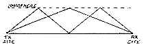
Figure
1. Multipath propagation causes fading when waves arrives
out of phase.
|
Multipath propagation
results in the signal being received by the listener over two or
more paths. A typical circuit is shown in Figure 1. One path consists
of a single, low angle hop from the transmitter to the receiver.
The other path consists of two hops at a higher angle. The two hop
path is physically longer than the single hop path. When the two
waves combine at the receiver' they can be in phase. In this case
the waves act to reinforce one another making the received signal
stronger. Because the delay difference is a function of the path
length difference, the waves can just as easily arrive out of phase
causing cancellation or what we normally call fading.
Wavelength is inversely proportional to frequency. The bandwidth
of an AM transmission is normally about 10 kHz. Sidebands extend
above and below the carrier frequency by 5 kHz or more. Waves arriving
via multiple paths can cancel at one frequency but not at another.
This effect gives rise to what is called ''selective fading". Selective
fading can result in the carrier fading while the sidebands remain
strong. The result is severe distortion similar to overmodulation.
Selective fading can also result in one sideband fading while the
other remains strong. Distortion also results from this condition.
The polarization of the signal after it passes through the
ionosphere is rotated by a phenomenon known as "Faraday Rotation".
Normally, the signal transmitted by the broadcaster is horizontally
polarized. (WWV is an exception to the rule; they use vertical polarization.)
This means that the electric field is parallel to the surface of
the Earth. When the wave transits the ionosphere, the presence of
free charged electrons and the Earth's magnetic field combine to
cause the electric field vector to rotate. Thus, the wave returns
to Earth with the electric field oriented randomly. When the receive
antenna wire is aligned parallel to the electric field vector, maximum
energy is captured from the passing wave. When the wire is oriented
perpendicular to the electric field vector, no energy transfer occurs.
As the orientation of the electric field vector shifts, the signal
fades up and down The amount of rotation of the electric field vector
at any instant is a function of frequency so selective fading can
occur at different frequencies within the signal bandwidth.
How can
the situation be improved?
International
broadcasters already attempt to minimize multipath propagation
by concentrating radiated energy at the horizon. Curtain antenna
arrays and rhombic antenna designs used by the big guns attempt
to minimize high angle minor lobes to reduce the amount of energy
reaching the receiver via more than one path.
FM broadcasters
have found that automobile reception fading is reduced by transmitting
circularly polarized waves. Circular polarization can be thought
of as simply horizontal and vertical radiation with a 90 phase
shift between the two polarizations. Although such transmissions
would seem to be beneficial in reducing polarization-induced fading
on HF paths, no international broadcasters are known to be using
this technique.
The effects
of selective fading can be minimized by the use of single sideband
(SSB) and synchronous detectors. Single sideband reception of
a double-sideband, AM signal allows the operator to select either
the sidebands above the carrier frequency (USB) or below the carrier
frequency (LSB). Ignoring the other sideband allows that sideband
to fade without contributing to distortion. The SSB receiver also
reconstructs the carrier. Selective fading of the carrier does
not contribute to SSB distortion because the carrier is filtered
out before the detector.
High fidelity
reception of SW signals using the SSB technique is not possible
for two reasons:
1. The frequency of the reconstructed carrier is not exactly
the same as the frequency of the transmitted carrier;
2. The frequency of the signal as received will wander
due to path length variations which result in Doppler shift.
Listen on 5 MHz some night when YVTO and WWV are both competing.
Beats of three or four Hz are clearly evident even though the
frequencies of both stations are controlled to better than one
thousandth of a Hz by atomic standards. The Doppler shift varies
erratically with time in an unpredictable manner. Three or four
Hz error does not bother voice intelligibility but would be noticeable
to a good ear on music.
Doppler
shift can be eliminated by allowing the reconstructed carrier
to track the incoming signal. This is where the synchronous detector
shines. Signals demodulated by a sync detector are not subject
to selective fading of the carrier as long as there is enough
carrier present to keep the detector locked. Long time constants
on the carrier tracking, phase locked loop allow the synchronous
detector to "fly wheel" through short carrier fades without losing
lock.
These distortion
causing effects can also be reduced by the use of diversity reception.
Harold Beverage of Beverage antenna fame died on January 27, 1993
at the age of 99. He had over 90 patents to his credit but the
two he was most proud of were the wave antenna, as he called it
originally, and diversity reception. There are three types of
diversity reception techniques which the SWL can use to minimize
fading and distortion:
1. Frequency diversity;
2. Spatial diversity;
3. Polarization diversity.
In all three
cases the same information is receive via redundant paths and
combined at the receiver site into a high quality signal.
Define
what is meant by frequent diversity
In frequency
diversity reception the same program material is received simultaneously
on two or more frequencies. If the frequencies are separated by
more than 100 kHz, the paths will likely fade at different times.
Let's say the BBC can be heard on 12.095 and 15.070 MHz. You will
need one receiver on each frequency. Combine the outputs and you
have frequency diversity reception. One caution must be observed.
The transmissions should originate from the same site. Relay stations
are typically fed by satellite circuits. Each satellite hop to
geosynchronous altitude results in a round trip time delay of
i/4 second. An annoying echo effect is all that will be heard
if the two frequencies do not originate at the same site.
How are
the signals combined?
There are
two general methods, pre-detection and post-detection, for combining
diversity signals. Pre-detection combining can have some signal-to-noise
ratio advantages but requires complex circuits and phase-stable
paths. Because ionosphere-reflected signals continuously shift
in phase as the path length changes, post detection combining
is the most practical technique for the SWL. One approach could
use the AGC voltage from each of two identical receivers to control
the switching logic. The logic would select the stronger signal
at any instant.
A simpler
approach would be to feed each receiver into the separate inputs
of a stereo audio system. The combining is then done in the listener's
brain. As fading occurs the aural image of the sound will appear
to wander between the two stereo speakers.
|
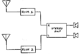
Figure
2. Two receivers, two antennas and a stereo amplifier makes
a poor-mans diversity reeiver.
|
This wandering
effect might at first be annoying but with a little "getting used
to'' will provide a dynamic demonstration of the variability of
ionospheric paths, If the listener finds this effect annoying, the
stereo amplifier can be configured for monaural operation. In any
case the gain of each receiver should be limited by use of the RF
gain control to avoid noisy, distorted audio during fades.
Such a system is depicted in block diagram form in Figure 2.
How does
spatial diversity work?
Spatial diversity
is based on the fact that if the signal is received on two antennas
separated from each other by more than a wavelength or so, the
fades will not be correlated. Fades on one antenna will not be
accompanied by simultaneous fades on the other antenna. In this
case both receivers shown in Figure 2 could be tuned to the same
frequency.
Another form
of spatial diversity can be obtained with a single receiver by
simply using a longwire antenna of more than one wavelength, The
theory here is that the large physical size of the antenna means
that somewhere on the wire the multipath waves are not canceling
so there will always be an output, Longwire antennas, mounted
high and in the clear, will exhibit gain and directivity at low
elevation angles, Because high angle multipath signals are discriminated
against by such an antenna, fading effects are reduced compared
to a half wave dipole or smaller antenna.
What is
polarization diversity?
Polarization
diversity allows the receiving system to extract energy from the
wave regardless of the orientation of the electric field vector.
One approach to polarization diversity is to orient the two antennas
in Figure 2 so that one antenna responds to horizontal fields
and the other responds to vertical fields.
|