|
Remotely controlled
Pennant antenna
By Mark
Connelly, WA1ION
July 19, 2000
The July 2000 issue of QST magazine published an article
by Earl W. Cunningham, K6SE,
entitled "Flags, Pennants, and Other Ground-Independent Low Band
Receiving Antennas".
The work presented in the article includes research by several
other hams including Jose, EA3VY.
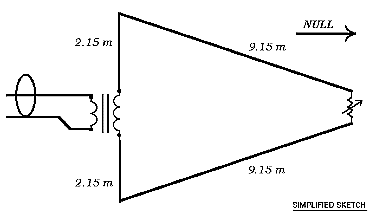
The class of antennas discussed comprises single-turn loops terminated
on the side opposite the feedpoint.
The termination effects a null off the end where the terminator
is located, thereby producing a cardioid (heart-shaped) directional
pick-up pattern.
The antenna is broadband rather than resonant. The pattern produced
holds up well over a wide frequency range.
Earl has run EZNEC computer simulations to calculate lengths which
give a non-reactive feedpoint impedance to ensure wideband coverage.
The dimensions of the antenna are small enough to permit installation
in the backyards of typical suburban residences. See the figure
above for pennant style antenna dimensions derived from computer
optimizations.
What I
have done to improve upon the original concept is to incorporate
the remote termination control methods previously used with great
success by Steve
Byan
for Beverage termination and, subsequently, by Al
Merriman
and Andy
Ikin,
for K9AY Loop termination. The merits of both of these prior implementations
have been conclusively validated in real-world experiences during
several Newfoundland
DXpeditions.
The
remotely-controlled resistance element is a "Vactrol", part number
VTL5C4, made by Perkin-Elmer,
formerly EG&G Vactec. It uses an LED optically coupled to
a photoresistor. At 0 mA through the LED, the photoresistor is
a high value, greater than 10K ohms. At 30 mA LED current, the
photoresistor value decreases to less than 60 ohms. Intermediate
values of LED current produce intermediate resistance values.
DC is fed to the LED through RF chokes to prevent undesired loading
effects at radio frequencies. DC blocking capacitors allow RF
to go through the photoresistor termination without letting DC
flow through it.
Remote control of the pennant's termination resistance
provides optimum null depth on the principal axis (in the direction
that points towards, and beyond, the termination as viewed from
the feedpoint).
Additionally, test data taken indicate that termination adjustment
allows a certain degree of null slewing up to about 45 degrees
off the principal null axis. Achievable null depth decreases as
a null is placed farther (in an angular sense) from the principal
axis, but slewing the null by using a slightly different termination
resistance can still produce a superior null in that direction
than if the deepest principal-axis null was used instead.
An example would be an antenna configured with the termination
west of the feedpoint. Station "A" is due west and station "B"
is northwest. With the termination adjusted for the typical 35
dB or better west null of Station "A", station "B" is down about
13 dB (based on the curves in Earl's article).
By slewing the null with a slightly different termination resistance,
the reduction of station "A" would deteriorate, but rejection
of "B" may be increased to 20 dB or so.
This finding has been determined by experimentation; I have no
formal simulation data to back it up.
In any event, there are differences in optimum termination resistance
which are affected by bearing, frequency, skip angle, weather,
stray coupling to external objects/structures, and imperfections
in the load at the feedpoint of the antenna. Because of these
variations in the resistance needed for each optimum null solution,
the ability to control the termination remotely is highly desirable,
just as in the case of the K9AY Loop.
Pennant
antennas seem to have a bit deeper null than Flag
antennas
(a rectangular version of the design), so the pennant will be
the main focus of this article.
Earl Cunningham's article goes into all the design permutations
and it gives detailed directional patterns. His use of all these
antenna types concentrates on their application in the 160, 80,
and 40 meter ham bands (1.8, 3.5, and 7 MHz).
I corresponded with Earl via e-mail to see if he could suggest
any alterations of the design for usage on medium-wave frequencies
(500 to 1800 kHz). He stated that the original dimensions would
work fine, just that the efficiency (sensitivity) would be low
and that amplification would be required to get gain anywhere
near that of slopers, longwires, dipoles, or other conventional
outdoor antennas.
See my BBVA-A
documentation
for an amplifier design which may be suitable.
Testing
Tests were performed at a site in West Yarmouth, MA as well as
at my home in Billerica, MA. Findings at both locations were similar.
At Billerica, maximum amplifier gain is limited because 50 kW
WRKO-680 is only 5 km / 3 miles away.
Amplifier or receiver overloading may be caused by WRKO and several
other locals including WNRB-1510.
Furthermore, the local electrical noise at Billerica (from nearby
TV's, light dimmers, computers, etc.) sometimes exceeds S9, making
weaker signal evaluation difficult or impossible. For these reasons,
the tables below represent measurements taken at the site on Trowbridge
Path in West Yarmouth (GC= 70.223 W / 41.682 N).
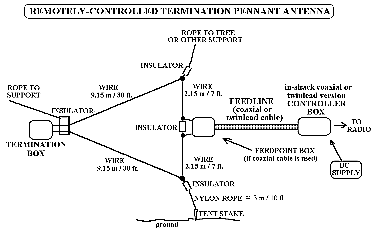
The vertical
portion of the antenna was supported by a nylon rope going
to the top of a 15 m / 50 ft. pitch pine tree.
The rope was adjusted for a bottom insulator height of about 3
m: that made the top insulator height about 7.3 m.
The bottom insulator was tied via nylon rope to a tent stake to
provide correct tension on the vertical section of the pendant.
The termination end, west of the feedpoint, was supported by a
plastic-hooked non-conductive bungee cord going to low branches
in another pine tree.
As direct measurement of termination resistance was not possible
during operation, the voltage measured at the arm of the controller's
potentiometer was recorded instead. Table
3
relates this voltage to the termination photoresistor's ohmic
value.
The test results show that the pennant antenna with remote
termination provides a cardioid pick-up pattern from a single
antenna without the need for a phasing unit.
Tests with a K9AY antenna in the same position at the West Yarmouth
site a month earlier showed best-case nulls of only about 15 dB.
The ground at the site is almost pure sand, so I'm sure that the
more-fussy grounding requirements of the K9AY degraded its performance.
The beauty of the pennant and similar designs is that ground conditions
do not have much effect on the achievable null depth. A properly-constructed
pennant should have at least 30 dB of null depth on the principal
axis even in situations as different as a salt-marsh or a pile
of rocks and sand.
Height of the pennant antenna doesn't have all that much effect
either (although I don't think that the bottom point should be
much lower than about 2 m / 6.6 ft.). The main benefit of raising
the antenna to a much greater height would be to reduce local
electrical noise and, perhaps, to increase sensitivity a bit in
poor-ground areas.
Coaxial Cable versus Twinlead feed
A system fed with 50 ohm coaxial cable requires Coaxial Controller,
Feedpoint, and Termination box assemblies.
The Feedpoint Box provides an impedance transformation from approximately
800 ohms antenna impedance to 50 ohms receiver input impedance.
This is done by means of a 16:1 RF transformer, Mini-Circuits
part number T16-6T-X65 or a suitable homebrew equivalent.
A system fed with 300 ohm twinlead requires just a Twinlead Controller
box and a Termination box. Twinlead goes from the controller straight
to the antenna feedpoint, at which it is connected directly to
the upper and lower wires of the pennant. The required impedance
transformer is located in the Twinlead Controller Box.
Maximum suggested twinlead feedline length is about 30 m (100
ft). Coaxially-fed systems can be located farther from the operating
position, perhaps as much as 100 m (328 ft) without a great amount
of signal loss below 2 MHz.
The layouts
of the Controller, Feedpoint, and Termination boxes are not critical.
Documentation presented herein is limited to electrical schematics.
Commonly-available parts are noted by value only. Unusual components
are noted with vendor stock numbers.
Test
data tables are for a coaxially-fed unamplified pennant
antenna (Table
1)
and for a twinlead-fed pennant system with a BBVA-A
amplifier providing about 30 dB of gain (Table
2).
Stations shown are a representative sample. For an "unabridged"
daytime bandscan available at Mark
Connelly's site.
|
For
a list of parts vendors I use often, check my vendors
web page.
The coaxially-fed
system exhibits nulls up to 36 dB with best performance at
about 290 degrees and the twinlead-fed system reaches 39 dB of
null depth with best performance near 270 degrees (i.e. due west).
I'm not sure how the feedline chosen has an effect on best null
angle, other than perhaps by unintended coupling to the antenna
element.
Null depth in the 250 - 330 degree bearing range is shown in Chart
1. This chart would have been extended down to 230 degrees for
symmetry, but there weren't enough suitable stations on 230 -
250 degree bearings to provide useful data.
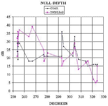
Chart 1: Null Depth
As noted
in the introductory discussion, the resistance required for a
null varies with the bearing of the null. Deepest nulls, in the
principal design direction of the antenna, occur with resistance
values of 700 to 1000 ohms. Depths of 30 dB or better, at least
on stable groundwave signals, can be expected within 10 degrees
of the optimum bearing with resistances in the 700 to 1000 ohm
window.
An interesting fact that came up, not mentioned in the K6SE article,
is that nulls can be "slewed" well off the principal axis, admittedly
with decreased null depth at greater bearing deviations.
Table
1
and Table
2,
and Chart 2 below, show that bearings counterclockwise (anticlockwise)
of optimum require null resistances greater than normal values.
Nulls on bearings clockwise of optimum require null resistance
values that are lower: down to about 300 ohms.
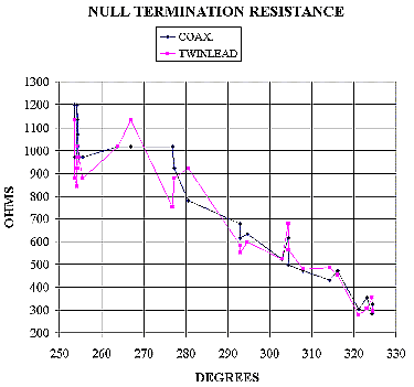
Chart 2: Null Resistance
Null resistances
were measured by measuring control voltage during reception tests
and then calibrating voltage versus resistance with the system
brought indoors (termination box opened up). Table
3
shows the calibration factors.
Phased
Arrays
Phased arrays
of pennants can be used to deepen the null (enhancing front-to-back
ratio) and to focus the pick-up area into a narrower lobe, approaching
Beverage-like tightness.
In situations such as the 160-m band, with a narrow overall bandwidth
to cover, one can make use of simple phasing methods, such as
specific feedline lengths acting as delay lines.
On the AM broadcast band, with a nearly 4 to 1 maximum to minimum
frequency ratio, a phasing unit offering continuous shifting over
360 degrees must be used. There are many units which will provide
this functionality: these include modified
versions
of the commercially-available MFJ-1026.
The simplest phased array would be two pennants spaced a minimum
of 1/12 wavelength and a maximum of 1/3 wavelength apart along
the desired peak-null axis.
A medium wave example: With signals to the west to be
eliminated, place two pennant antennas about 50 m (164 ft.) apart
on an east-west line.
First, configure each antenna for best-possible cardioids nulling
west.
Present the two antennas' contributions to the phasing unit's
inputs and then adjust the phase and amplitude controls to remove
whatever vestiges of western signals that are still there to interfere
with desired DX stations from the northeast, east, and southeast.
See Phased
Arrays
for further discussions of phased arrays.
Electrical Noise Considerations
As noted
previously, local electrical noise can be reduced by trying different
heights of the pennant system above ground. The pennant, like
the K9AY, sums electrical (E) and magnetic (H) field pick-ups
to produce a cardioid pattern.
This is similar to using an active whip and a broadband magnetic
loop as the two inputs to a phasing unit: that's what I typically
use on car DXpeditions.
Since
the electrical field pick-up often contains locally-generated
noise to a greater extent than what's intercepted by a balanced
magnetic field loop antenna, combined E-field / H-field systems
like the pennant, K9AY, or Ewe might not be as "quiet" or as usable
as a traditional loop for weak-signal work in average residential
areas. Two or more magnetic loops used as elements of a phased
array can create cardioid directionality with less local noise
pick-up; the price you pay is greater null adjustment complexity
as contrasted with the pennant or similar single-antenna system.
Conclusions
At most sites,
the pennant antenna offers a simple single-antenna method of producing
a cardioid pattern.
Use of a remotely-controlled termination resistance allows a degree
of slewing the null bearing and depth to reduce interference from
numerous stations in the approximate opposite direction of DX
targets being chased.
In many cases, especially when grounding for a K9AY system is
inadequate, the pennant represents the best receiving-antenna
solution at sites having limited space.
Construction
Drawings
Overall View of Antenna System
Click
here for larger image
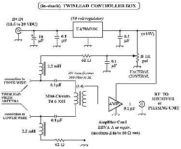
Twinlead Controller Box
Click
here for larger image
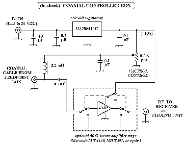
Coaxial
Controller Box
Click
here for larger image
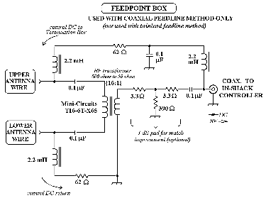
Feedpoint Box (for Coaxially-Fed System)
Click
here for larger image
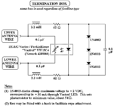
Termination
Box
Click
here for larger image
For downloading:
Article
as PDF document
Article
as Microsoft Word document (zipped)
|


![]()


![]()